

Hey everyone this particular wiring diagram is currently working fine on my 1985 Celica Supra P-Type. Although is not guaranteed to be perfect, no problems have arisen yet. Of course you need to check this against your ECU pinouts compared to what I have used here. If you have a manual, don't try to jumper the automatic range selector... you ain't got one. etc. Just use a bit of common sense and read what others have posted over the years. I rarely update the thread and that probably isn't going to change anytime soon.
Specs of donor car:
1994 Lexus GS300
2JZ-GE Automatic
xxxxxxxxxx miles")
IK1 and IK2 wiring explanation
Alright shall we? Let's start with the Large IK1/IK2 connector as it's probably the easiest.
Here is a pin-out listing what each pins function is. I have highlighted in Red the pins you'll need.
![Image]()
E3 EFI Main Relay B+ Black/Red (Main function(s) Idle Air Control)
F6 IG2 Relay Black/Orange (Main functions(s) Injectors and Ignitor/coil)
F9 water temp. sender Yellow/Green (Main function(s) Temperature display)
F12 tachometer IG- Black (Main Function(s) RPM display)
E3 and F6 need to be connected to a 12V power supply. I took the engine wiring harness apart and removed all the un needed automatic stuffs. At that time I also relocated wires E3 Black/Red and F6 Black/Orange . They were moved Closer to the Intake manifold so they would reach their respective plugs without adding extra wire.
Updated 26MAY2024:
Do not move the Black/Red E3 pin towards the intake. As many have suggested and MrBubbles00482 has found the correct wiring solution. The idle air control needs to have time to reset after the engine is shut off. Please do as MrBubbles00482 has suggested and connect it to the second B+ wire available on the body harness.
E3 EFI Main Relay B+ Black/Red (Main function(s) Idle Air Control)
E3 black red to B+ on body harness connector
For E3 I used the power supply to the 5M-GE's Ignitor. Simply cut a good plug from a Ignitor and solder it to the Black/Red E3 wire. Plug it in and you will now have powered up your Idle air Control :good:.
![Image]()
F6 IG2 Relay Black/Orange (Main functions(s) Injectors and Ignitor/coil)
F6 utilizes the same concept, except we use the power supply to the 5M-GE's Resistor Pack. All you have to do is cut a good supply plug from a Resistor pack. Then solder it to the Black/Orange F6 wire. Once plugged in you'll have successfully powered up your Injectors and Ignitor/Coil.
![Image]()
F9 water temp. sender Yellow/Green (Main function(s) Temperature display)
F9 will be soldered into your/donor 5M-GE engine harness to body plug. Simply solder F9 Yellow/Green to the Yellow/Green wire of the body plug. Plug the two connectors together and you'll have a temp gauge.
![Image]()
F12 tachometer IG- Black (Main Function(s) RPM display)
F12 is probably the least fun as there is no easy way to do it. For you tach signal you must solder a good size (length not gauge) wire lead to the Black F12 wire. After that is done snake the wire through the dash and connect to the Black wire coming out of the Cluster. I used quick connectors for this job and it worked quite well.
No pictures..
Note I did not go into to much depth on this as there is a bit of disassembly to be done. Just the basics of what wire needs to go where and how.
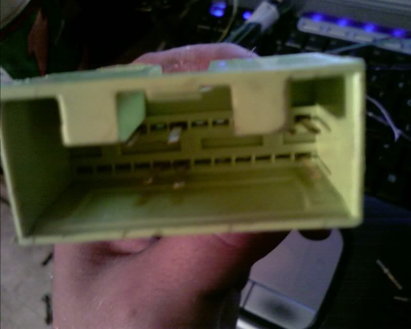
Ok now that we have taken car of the IK1 and IK2 connectors we well move on to the ECU to Body plug wiring.
24-pin body plug/single 40-pin ecu plug
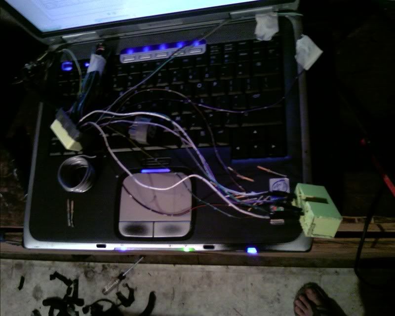
In order to retain the plug and play capability I took apart a 5M-GE ECU and removed the large 24-pin connector. Seen below assembled..
![Image]()
![Image]()
![Image]()
![Image]()
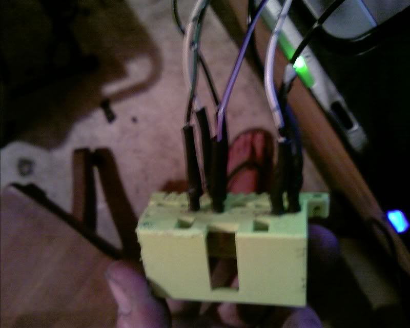
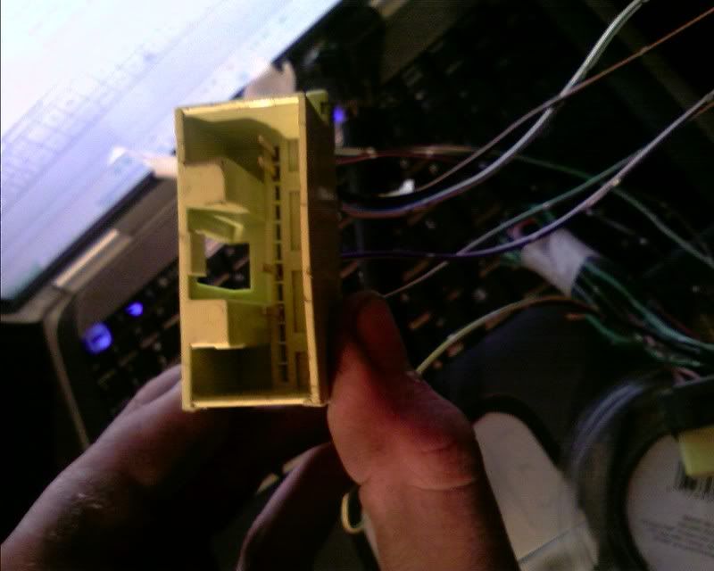
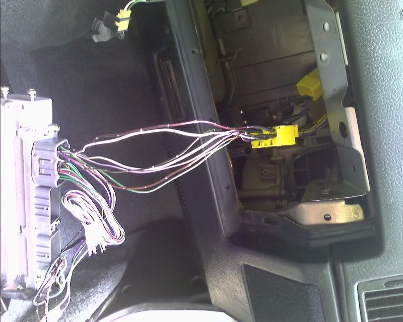
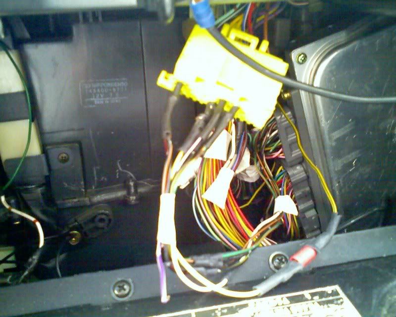
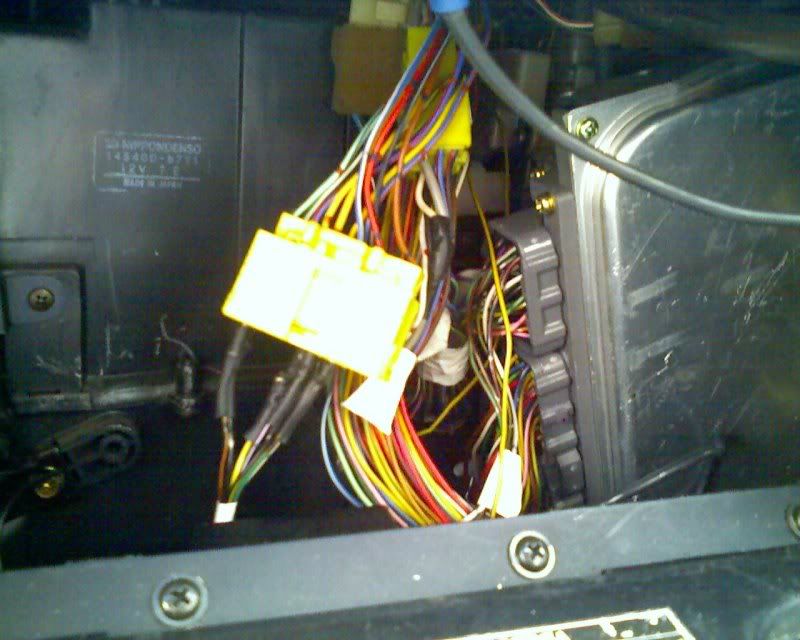
I have color coded for you what wire from the 2JZ-GE ECU needs to go to which pin on the connector. You simply must find the wire on the 2JZ-GE ECU and match it to the corresponding color for the pin. If needed I can post the Color of each wire.
2JZ-GE ECU pin-out
![Image]()
5M-GE ECU pin-out
![Image]()
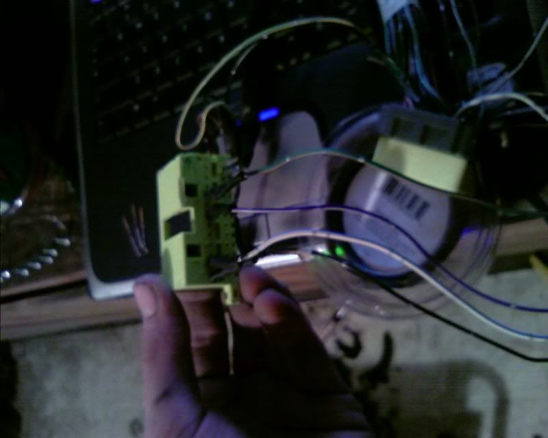
Match the colors and you are set, once you have this done it should look something like this.
Hit that +B on the LEFT of the outlined +B for the power of the outlined in red for E3 12v power.
note the extra wires were de-pinned to give a clean look.
![Image]()
![Image]()
![Image]()
![Image]()
![Image]()
Plug it in and you'll have a working ECU set that will control the engine A ok
Now that last portion of the job... The starter wire, This is very easy!! You just use the Mk.II's stock starter circuit. In order to use it with the Lexus starter, you have to cut the signal wire from the 2JZ-GE engine harness. Then you will solder it on the Mk.II's stock signal wire. Plug it in!!
[img} pictures coming... [/img]
Fuel pump wiring, non accident safe quick wiring.. You just need to jump the Fuel pump check connector and the fuel pump will turn on anytime the key is in the on position.
I do have a accident safe solution, but haven't had time to buy and wire that pieces.
Tie up any other lose ends
Turn it over and wait for the music of the engine to start pouring over you.
BTW: Like Brain (Lacrussgus14) said, the 2JZ-GTE harness is the same. I'm confirming this through the wiring of a Aristo 2JZ-GTE and so far I've had no problems. So if a mod would like to change the title to 2JZ-GTE & 2JZ-GE PnP wiring guide, feel free.
Questions? Comments? post away!
Credits:
Kenny (sarinas_dragons) -- 2JZ-GE ECU pin-out
TSRM (cygnusx1.net) -- 5M-GE ECU pin-out
Punkra -- IK1 and IK2 pin-out
Brain (Lacrussgus14) -- Inspiration
MrBubbles00482 -- ISCV proper wiring
and many other people I gathered info from
:good: thank you all
Now back to work on the 2JZ-GTE (<--- haha was a joke! that car has been sitting on the jack stands for 12 years now or October of 2012................. FML)
More images I have in my files that may be useful, I don't know anymore..
<The images weren't useful and served to cause more confusion so they were removed... but still in the insets and imgur.>
ATTN: all photos can be found here incase they go missing again.
Specs of donor car:
1994 Lexus GS300
2JZ-GE Automatic
xxxxxxxxxx miles
IK1 and IK2 wiring explanation
Alright shall we? Let's start with the Large IK1/IK2 connector as it's probably the easiest.
Here is a pin-out listing what each pins function is. I have highlighted in Red the pins you'll need.
E3 EFI Main Relay B+ Black/Red (Main function(s) Idle Air Control)
F6 IG2 Relay Black/Orange (Main functions(s) Injectors and Ignitor/coil)
F9 water temp. sender Yellow/Green (Main function(s) Temperature display)
F12 tachometer IG- Black (Main Function(s) RPM display)
E3 and F6 need to be connected to a 12V power supply.
Updated 26MAY2024:
Do not move the Black/Red E3 pin towards the intake. As many have suggested and MrBubbles00482 has found the correct wiring solution. The idle air control needs to have time to reset after the engine is shut off. Please do as MrBubbles00482 has suggested and connect it to the second B+ wire available on the body harness.
E3 EFI Main Relay B+ Black/Red (Main function(s) Idle Air Control)
E3 black red to B+ on body harness connector
F6 IG2 Relay Black/Orange (Main functions(s) Injectors and Ignitor/coil)
F6 utilizes the same concept, except we use the power supply to the 5M-GE's Resistor Pack. All you have to do is cut a good supply plug from a Resistor pack. Then solder it to the Black/Orange F6 wire. Once plugged in you'll have successfully powered up your Injectors and Ignitor/Coil
.F9 water temp. sender Yellow/Green (Main function(s) Temperature display)
F9 will be soldered into your/donor 5M-GE engine harness to body plug. Simply solder F9 Yellow/Green to the Yellow/Green wire of the body plug. Plug the two connectors together and you'll have a temp gauge
.F12 tachometer IG- Black (Main Function(s) RPM display)
F12 is probably the least fun as there is no easy way to do it. For you tach signal you must solder a good size (length not gauge) wire lead to the Black F12 wire. After that is done snake the wire through the dash and connect to the Black wire coming out of the Cluster. I used quick connectors for this job and it worked quite well.
No pictures..
Note I did not go into to much depth on this as there is a bit of disassembly to be done. Just the basics of what wire needs to go where and how.
Ok now that we have taken car of the IK1 and IK2 connectors we well move on to the ECU to Body plug wiring.
24-pin body plug/single 40-pin ecu plug
In order to retain the plug and play capability I took apart a 5M-GE ECU and removed the large 24-pin connector. Seen below assembled..
I have color coded for you what wire from the 2JZ-GE ECU needs to go to which pin on the connector. You simply must find the wire on the 2JZ-GE ECU and match it to the corresponding color for the pin. If needed I can post the Color of each wire.
2JZ-GE ECU pin-out
5M-GE ECU pin-out
Match the colors and you are set, once you have this done it should look something like this.
Hit that +B on the LEFT of the outlined +B for the power of the outlined in red for E3 12v power.
note the extra wires were de-pinned to give a clean look.

Plug it in and you'll have a working ECU set that will control the engine A ok
Now that last portion of the job... The starter wire, This is very easy!! You just use the Mk.II's stock starter circuit. In order to use it with the Lexus starter, you have to cut the signal wire from the 2JZ-GE engine harness. Then you will solder it on the Mk.II's stock signal wire. Plug it in!!
[img} pictures coming... [/img]
Fuel pump wiring, non accident safe quick wiring.. You just need to jump the Fuel pump check connector and the fuel pump will turn on anytime the key is in the on position.
I do have a accident safe solution, but haven't had time to buy and wire that pieces.
Tie up any other lose ends
Turn it over and wait for the music of the engine to start pouring over you.
BTW: Like Brain (Lacrussgus14) said, the 2JZ-GTE harness is the same. I'm confirming this through the wiring of a Aristo 2JZ-GTE and so far I've had no problems. So if a mod would like to change the title to 2JZ-GTE & 2JZ-GE PnP wiring guide, feel free.
Questions? Comments? post away!
Credits:
Kenny (sarinas_dragons) -- 2JZ-GE ECU pin-out
TSRM (cygnusx1.net) -- 5M-GE ECU pin-out
Punkra -- IK1 and IK2 pin-out
Brain (Lacrussgus14) -- Inspiration
MrBubbles00482 -- ISCV proper wiring
and many other people I gathered info from
:good: thank you all
Now back to work on the 2JZ-GTE
(<--- haha was a joke! that car has been sitting on the jack stands for 12 years now or October of 2012................. FML)<The images weren't useful and served to cause more confusion so they were removed... but still in the insets and imgur.>
ATTN: all photos can be found here incase they go missing again.


